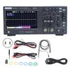
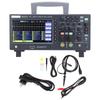
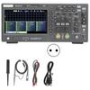
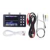
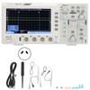
Feature:
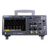
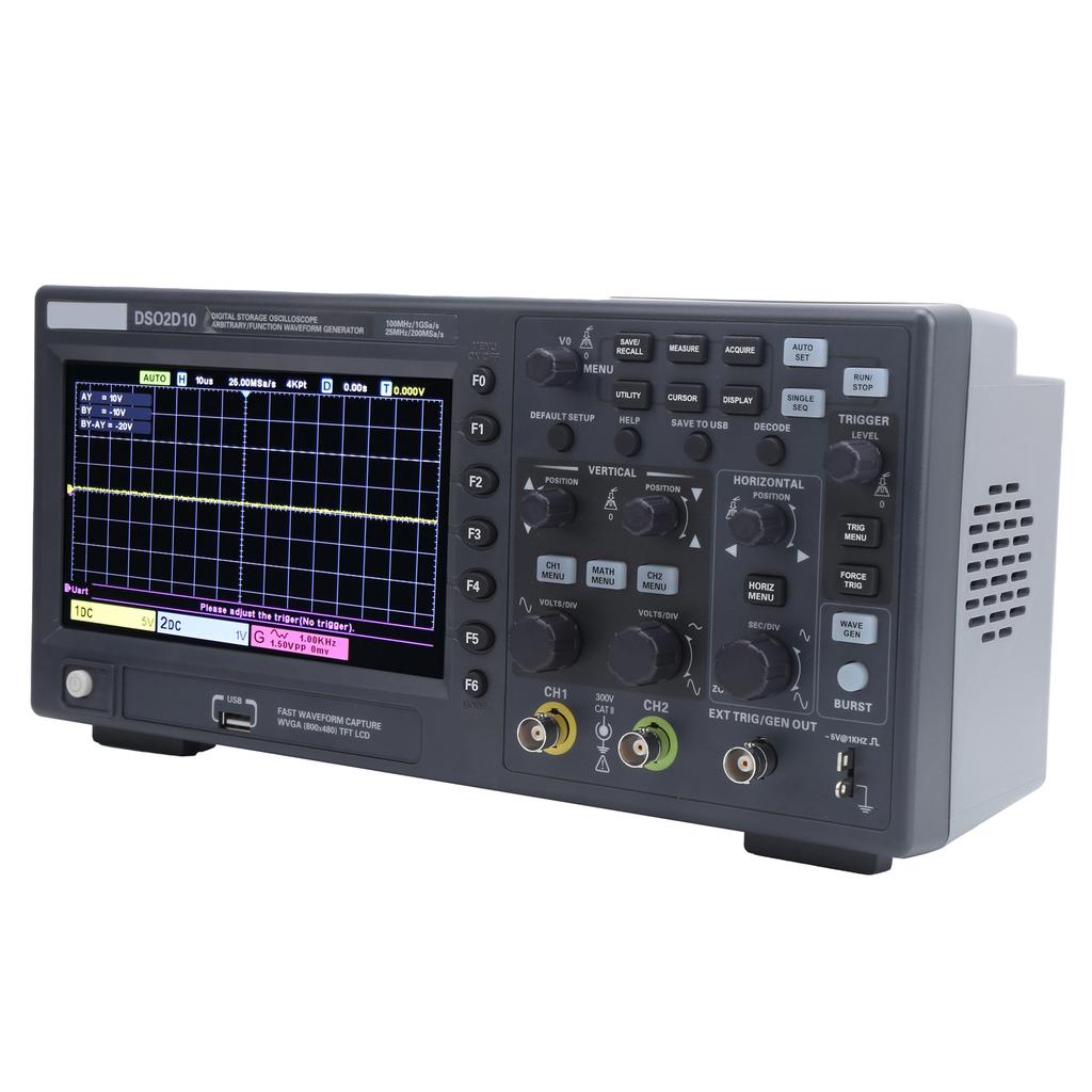
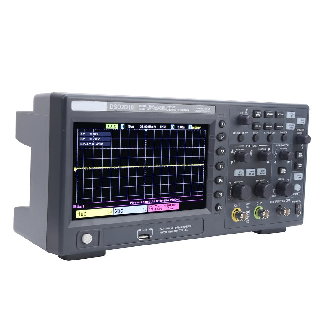
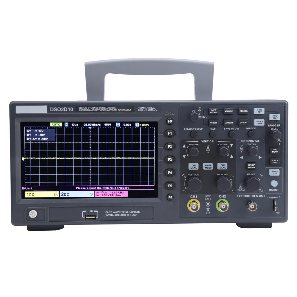
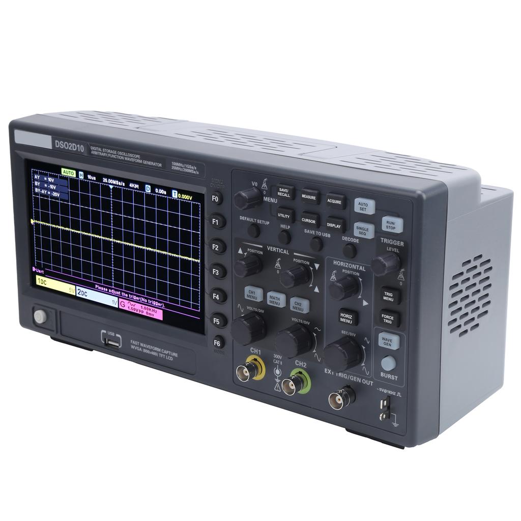
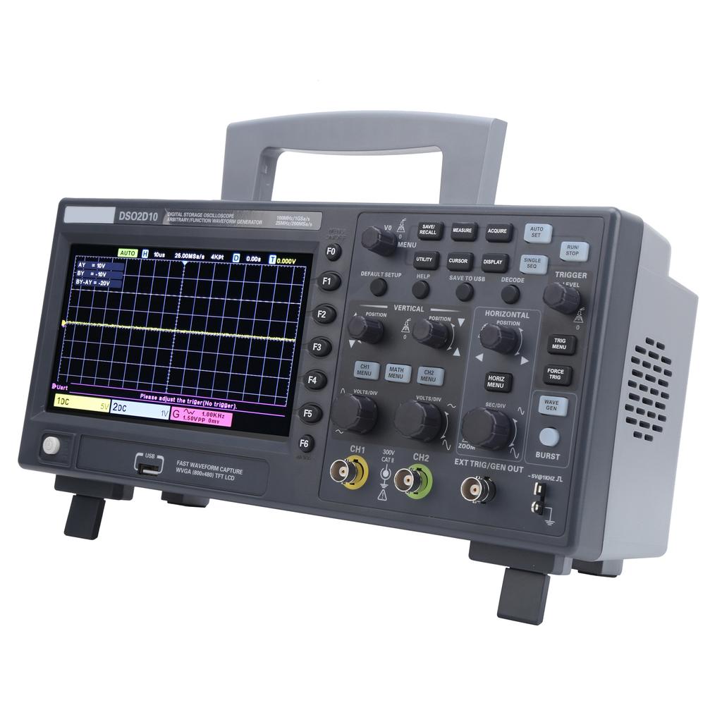
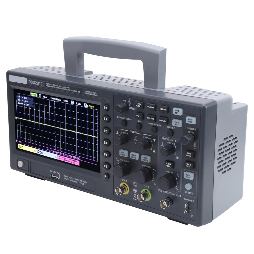
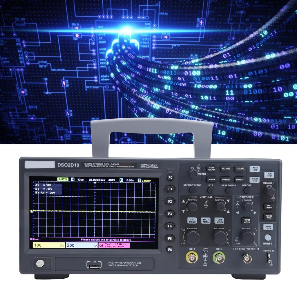
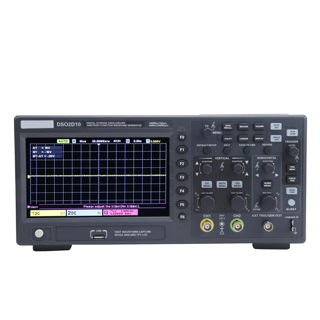
1. Digital storage oscilloscope, built‑in 1CH 25MHz signal generator, which makes electronic maintenance and car maintenance more convenient.
2. Abundant SCPI remote control commands. Storage depth is 8Mpts.
3. Trigger: edge, pulse, video, slope, timeout, window, pattern, interval, runt, UART, LIN, CAN, SPI, IIC.
4. It can save settings, waveforms, reference waveforms, CSV, pictures and other data formats.
5. Support threshold test, realize free measurement in the screen.
Specification:
Item Type: Digital Storage Oscilloscope
Material: ABS
Weight: Approx. 2700g 95.2oz
ModelDS02D10
Bandwidth100MHZ
Number of Oscilloscope Channels2CH
Built In Signal Source1CH
Oscilloscope index
Sampling Rate Range 1GSa a (single channel), 500Msa s
Collection Method
SamplingSampling Data
Peakdisplay high frequency and random glitch
Averagenumber of average waveforms: 4, 8, 16, 32, 64, 128
High Accuracyup to 12bit
Input
Input coupling DC, AC or ground (DC, AC, GND)
Input impedance1M Ohm + 2percent II20pF+ 3PF
Probe attenuation coefficient setting1X, 10X, 100X, 1000X
Voltage level300V CATII
Maximum input voltage300V RMS(10X)
Horizontal system
Waveform interpolation(sinX) X
Maximum record length Single channel: maximum 8M
Dual channels: maximum 4M
Horizontal scale range 2ns div 100s div, 1, 2, 5 steps
Time base modeX T, X Y, Roll
Zero offset + 0.5divX minimum time base gear
Trigger
Trigger mode:automatic, normal, single
Trigger typeedge trigger, pulse width trigger
Video trigger, slope trigger, timeout trigger
Window trigger, pattern trigger, interval trigger, runt trigger, UART trigger, LIN trigger, CAN trigger, IIC trigger
Measure
CursorVoltage difference between cursors△V
Time difference between cursors△T
The reciprocal of △T, in for Hertz (1 △T)
Automatic measurementdouble peak value, frequency, average value, maximum value, minimum value, period, top value, middle value, bottom value, amplitude, root mean square, rising edge overshoot, falling edge preshoot, period root mean square, period Average value, rise time, fall time, positive pulse width, negative pulse width, positive duty cycle, negative duty cycle, FRR, for FFF, falling edge overshoot, rising edge preshoot, pulse width, FRF, FFR, LRR, LRF, LFR, LFF
Digital Voltmeter Data Source CH1 CH2
Measurement type DC RMS, AC RMS, DC
Frequency meter hardware 6 bits
Computation
Data source CH1 CH2
Operator=+, , *, ÷, FFT
FFTpoints1024
Windowrectangular, for Hanning, for Heming, for Blackman,for Bartlett, flat roof
display high frequency and random glitchalone or full display
Vertical scaledB, VRms
Store
Save recall (non volatile) 9 types of files can be saved and recalled internally, including settings, waveforms, and references
Save to external memoryCSV file, BMP picture (24 bits)
Arbitrary Waveform Generator
Channel1
Sampling Rate Range 200MSa sec
Vertical resolution 12 bits
Maximum frequency 25MHZ
Standard WaveformSine wave, square wave, ramp wave, Exp, noise, DC
Arbitrary waveform Arb1, Arb2, Arb3, Arb4
Sine wave frequency range 0.1Hz 25MHz
Square wave frequency range 0.1Hz 10MHz
Duty ratio1percent 99percent
Triangular wave frequency range0.1Hz 1MHz
Symmetry0percent 100percent
Exponential wavefrequency range0.1Hz 5MHz
Noise bandwidth more than 25MHz
DCoffset 1.75V (50 Ohm ), 3.5V (high resistance)
Arbitrary wavefrequency range1uHz 25MHz
Wave length4096
Support PC download and external memory recall
Output impedance50 Ohm +1percent , high impedance
Amplitude5mV 3.5Vpp(50 Ohm )
10mV 7Vpp (high resistance)
Amplitude accuracy + 3dB
Frequency resolution1uHz
Wave depth4KSa
Frequency accuracy<10KHz,100ppm
>10KHz,50ppm
ModulationFMmodulation waveform Sine wave, square wave, triangular wave
Modulation frequency1Hz 50KHz
Modulation deviation 0.1Hz carrier frequency
AMmodulation waveform Sine wave, square wave, triangular wave
Modulation frequency1Hz 50KHz
Modulation depth0percent 120percent
BursttypeMulti period, infinite
Number of cycles 1 1024
Trigger source manual
Trigger input signal source
LevelCMOS
Probe compensator output
Output voltage, typically 5V, input load more than 1M Ohm
Frequency, typically1kHz+ 1percent
Show
Display type 7in TFT LCD screen diagonally
Display resolution800 (horizontal) x 480 (vertical) pixels
Display typepoint, vector
Waveform brightnessadjustable
Grid type adjustable
Grid brightnessadjustable
screen brightnessadjustable
Afterglow1s, 5s, 10s, 30s, infinite
Interface
Standard interface USB Host, USB Device
power supply
Power supply voltageAC 100 240 RMS(+ 10percent ), 45Hz 66Hz
Power consumption<15W
FuseT2A 250VAC
Environment
Operating temperature0 50 celsius (32 122 Fahrenheit )
Storage temperature 40 +71 celsius ( 40 159.8 Fahrenheit )
Temperature and humidity less than +104 Fahrenheit ( less than +40 celsius ): less than 90percent relative humidity
106 Fahrenheit 122 Fahrenheit (+41 celsius 50 celsius ): less than 60percent relative humidity
How to Use:
1: Plug in the power and turn on
2: Set the switch on the probe to X10 and connect the probe to channel 1 of the oscilloscope. To do this, align the slot on the probe connector with the protrusion on the CH1 BNC, press it down to connect, then turn to the right to lock the probe in place, and connect the probe tip and reference to the probe element On the connector, the label on the panel is: 5V@lKHz.
3: Press the Auto Set button. The screen shows a square wave with a frequency of 1kHz and a voltage of 5V peak to peak.
4: Observe whether it is a square wave, adjust the probe to keep the probe in the best state (the waveform is normal).
5: Measurement
Operating Instructions of the Signal Generator
1. Connect EXT TRIG GEN OUT and connect the other end to the unit that needs to receive signals
2. Press WAVE GEN to start the signal generator. Press F1 to select waveform, sine, square wave, DC, etc. (standard wave)
3. Press WAVE GEN, F2 frequency, period selection, F3 amplitude selection
4. Confirm the waveform emission.
.
Package List:
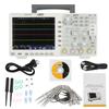
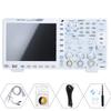
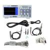
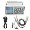
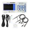
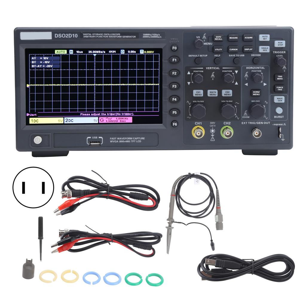
1 x Oscilloscope1 x Power Cord1 x USB Data Cable2 x BNC Cable1 x Adjustment1 x IC Cap6 x Color Circle1 x Oscilloscope Probe1 x Manual


 No-delivery refund