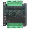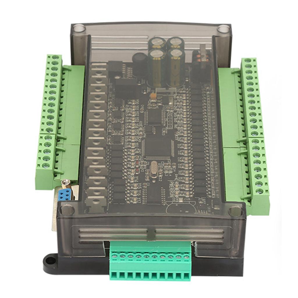
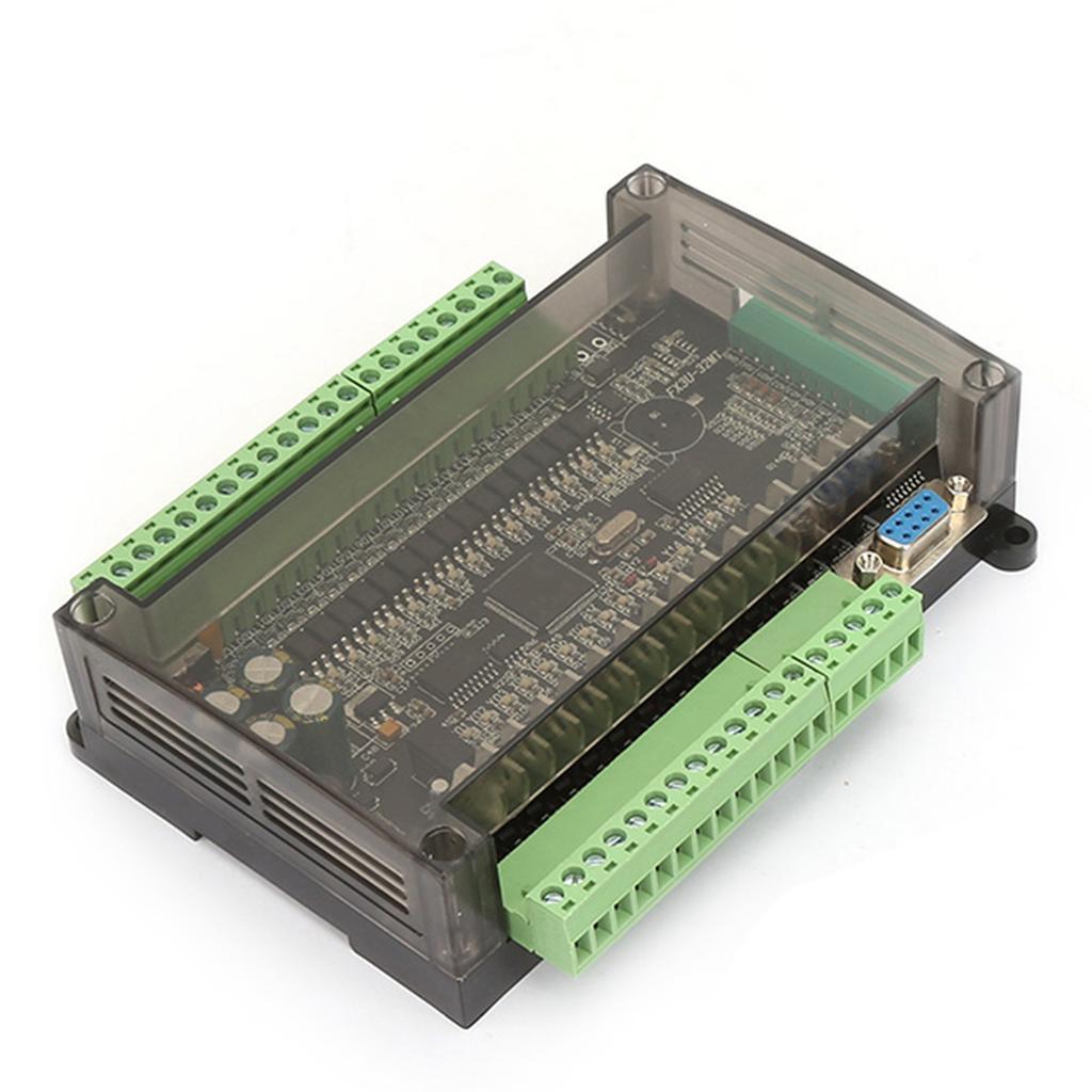
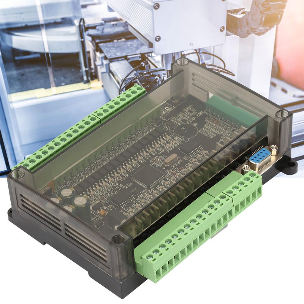
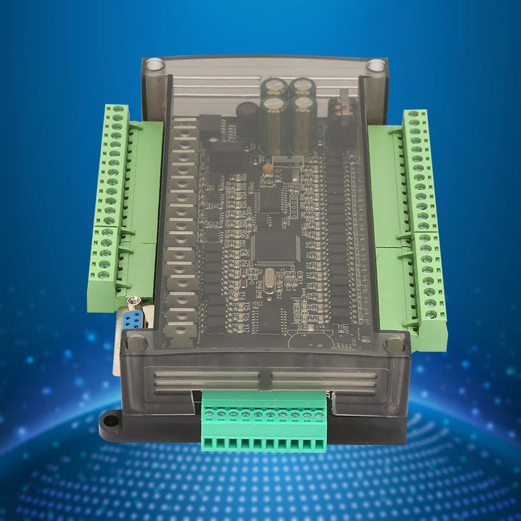
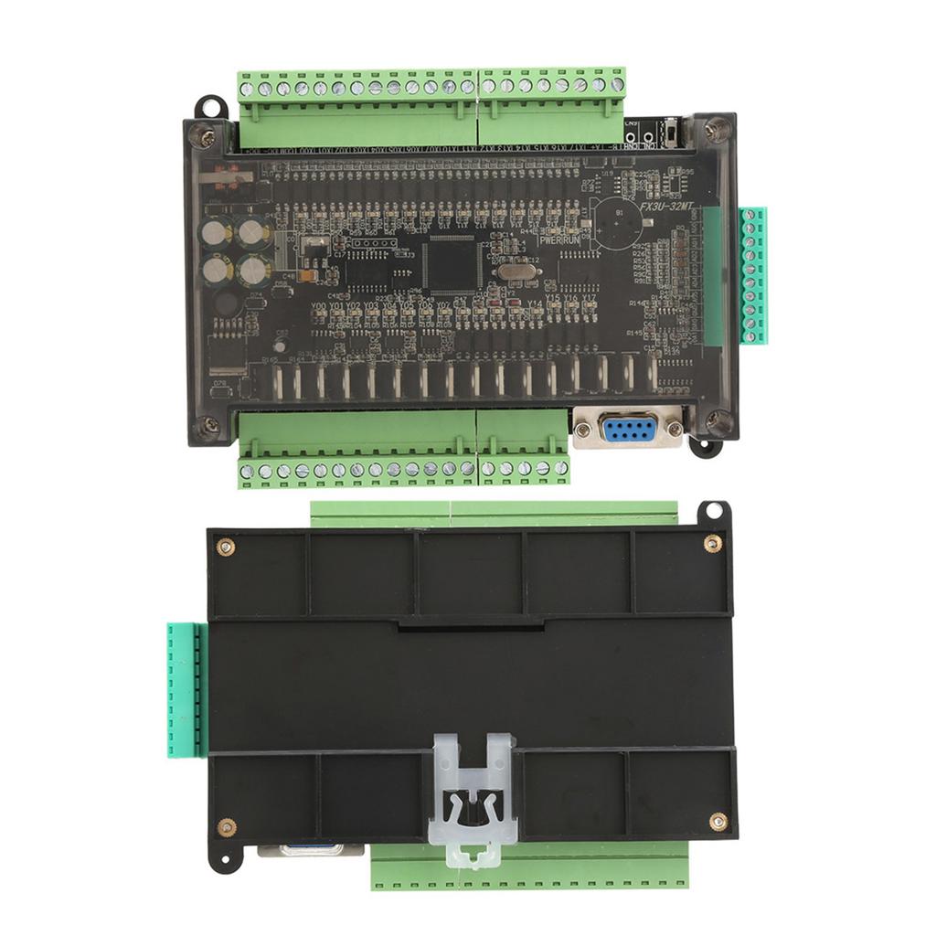
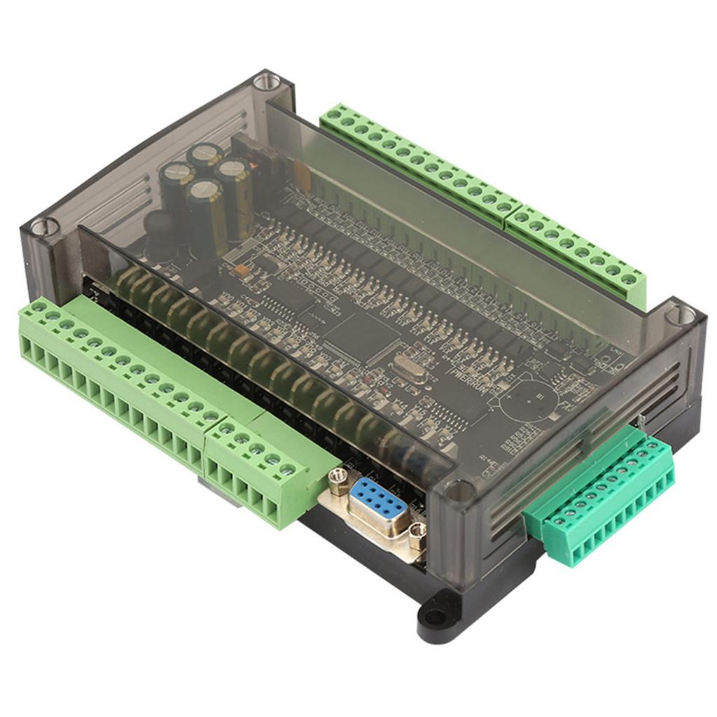
24V 32MT PLC Controller 8 Channel 100k Pulse 32bit MCU 16 Input 16 Transistor Output


Descrizione
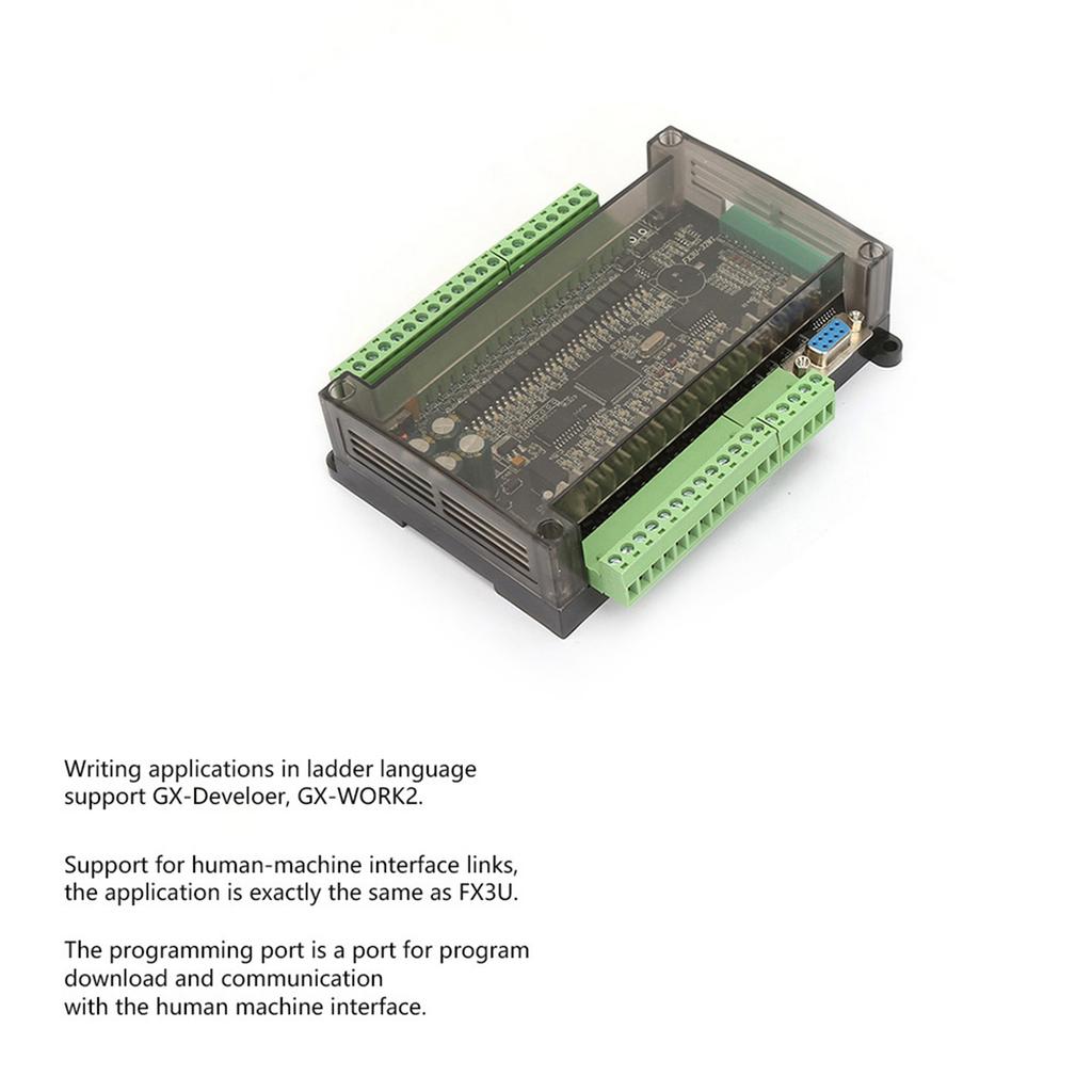
Features: Writing applications in ladder language support GX Develoer, GX WORK2. Support for human machine interface links, the application is exactly the same as FX3U. Support ladder programming, download, monitor. The programming port is a port for program download and communication with the human machine interface. This PLC adopts industrial grade 32 bit MCU with strong anti interference, and its running speed far exceeds the original FX3U. This PLC transmission baud rate is 38400. 16 point input and 16 transistor output of the board. Y0 Y7 transistor can output up to 100K pulse. Y0 Y16 can also be used as a normal output. If Y0 Y7 is connected to a large load, a freewheeling diode is required. 6AD input (3 channels 0 10V plus 3 channels 0 20MA), 2DA output (2 channels 0 10V output). The board is powered by DC 24V. Do not input AC or 220V voltage. Specification: Baud Rate:38400 Power Source: 24VDC Input power DC 24V Number of steps 8000 steps; 2 communication port: 1 RS232 (DB9 serial port communication port is FX3u protocol 38400, 7, E, 1;1 RS485 port, 4 communication protocols can be set through D8120. Input point X component XO X17, DC24 input, active low. X0 5 is the high speed counting input port (default is 12K, 100KHZ is optional) Input point Y component YO Y17 is the transistor output, and YO Y7 can output 8 100K pulses or 6 PWM pulse signals. The maximum current is 3A.YO 3 is the high speed output port (up to 100K). The PWM period is 0 32767 US. The maximum speed of the high speed port is 3A. The external load is connected to the common terminal +24, and the other end is connected to the PLC output port Y. Analog input 6 analog inputs, 12 bit accuracy, 3 channels 0 10V+3 channels 0 20mA, read with RD3A. Analog output 2 analog outputs, 12 bit accuracy, output voltage: 0 10V. Output analog voltage with WR3A command Intermediate relay M MO M3071, power down storage range can be set Step point S SO 1023, the power saving range can be set to S0 S1023 100Ms timer TO T199, cumulative power down save T184 T199 10Ms timer T200 T249, cumulative power down save T246 T249 1Ms timer T250 T383, where T250 255 is cumulative 16 bit counter CO C199, save power C100 199 32 bit counter C200 C219, save power C220 C234 32 bit high speed counter C235 255; C235 240 is a single phase counter, no multiplier; C241 240 is a single phase counter, 2 times the frequency; Register D C247 249 is a two phase counter, not multiplier; C250 252 is a two phase counter, 2 times frequency; C253 255 is a two phase counter, 4 times frequency; DO D7999, power down storage range can be set to DO 7999, Indirect addressing pointer V, Z VO 7, Z0 7 P subroutine jump number PO 63 I interrupt XO 5 is interrupted outside. Timer interrupt (1MS is the unit). Counter interrupt Special M component M8000 is normally closed when running, M8002 is powered on pulse, M8011 is 10Ms pulse, M8012 is 100Ms pulse, M8013 is 1s pulse, M8014 is minute pulse. Mnemonic, name Function LD Operation starts normally open contact LDI Operation starts normally closed contact LDP Rising edge detection operation starts LDF The falling edge detection operation starts AND Series normally open contacts ANI Series normally closed contacts ANDP Check the serial connection on the upper edge ANDF Falling edge detection serial connection OR Parallel normally open contact ORI Parallel normally closed contact ORP Rising edge detected parallel connection ORF Falling edge detection parallel connection ANB Series connection between circuit blocks ORB Parallel connection between circuit blocks OUT Coil output drive SET Coil action remains RST Remove line wet motion retention PLS Coil rising edge output PLF Coil falling edge output ALT Alternate output MC Common string connection point with coil command MCR Common contact release command MPS Operational storage MRD Storage readout MPP Storage readout and reset INV The operation result is reversed END End of program 4 step ladder instructions STL Step ladder start CALL Call subroutine RET Step ladder end SRET Subroutine return Package List: 1 x PLC Controller 1 x DB9 Serial Port Cord Note:
.