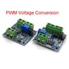
Signal Generator PWM Pulse Frequency Duty Cycle Adjustable Module LCD Display 1Hz-150Khz 3.3V-30V PWM Board Module
Farba a veľkosť


 Vrátenie peňazí za nedoručenieZáruka kvalityBezpečná logistikaOchrana súkromia
Popis
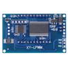
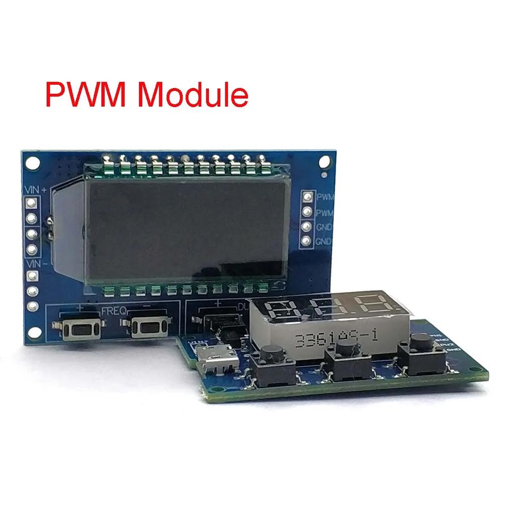
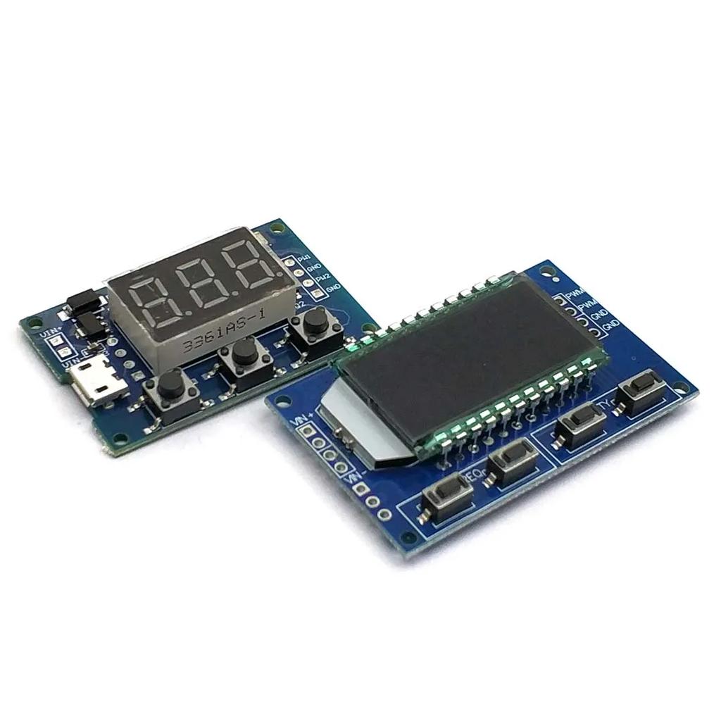
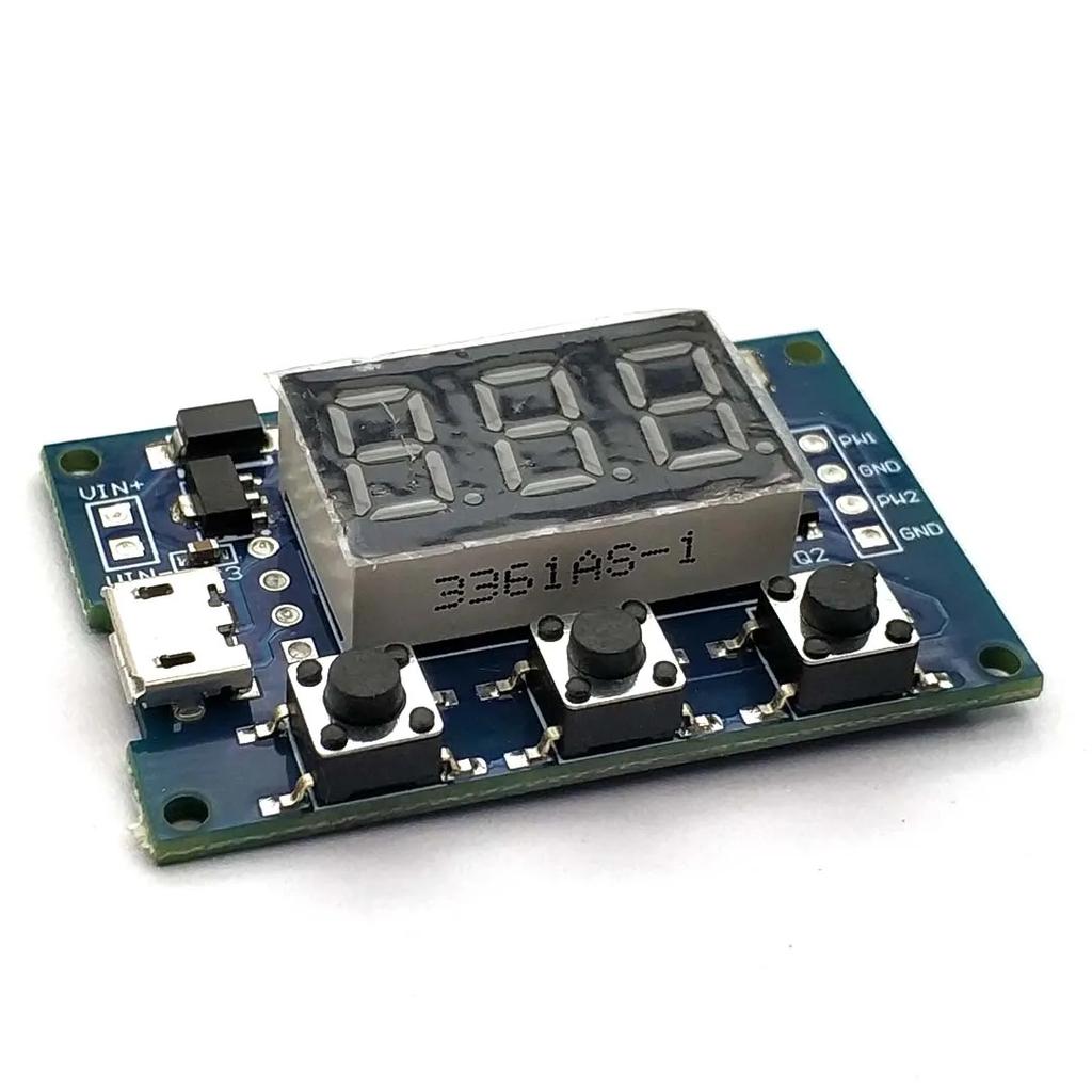
Type 1: 1. Two independent PWM outputs, which can be set separately for frequency and duty cycle; 2. Wide frequency range and high accuracy; 3. Capable of serial communication Boundary dimension: 41 * 28mm Thickness: 1.6mm
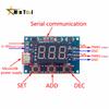
1, Module Description Two independent PWM outputs can be set separately for frequency and duty cycle; The frequency is divided into three ranges: 1. XXX (without Decimal separator): the small unit is 1Hz, and the value range is 1Hz~999Hz; 2. XX. X (the Decimal separator is in the tenth place): the small unit is 0.1Khz; Value range: 0.1KHz~99.9KHz 3. X.X.X. (three digits have Decimal separator): the small unit is 1 Khz; Value range: 1KHz~150KHz e. G. Frequency display: 100 represents PWM output of 100Hz pulses; 54.1 represents a pulse with PWM output of 54.1KHz; 1.2.4. Represents a pulse with PWM output of 124KHz Duty cycle value range: 0-100; Three frequency ranges share a common duty cycle, all set parameters are saved after power failure. 2, Parameter settings The module has three buttons: Set, Up, and Down; 1. By briefly pressing the [Set] key, switch to display four parameter values (FR1: frequency of PWM1; dU1: duty cycle of PWM1; FR2: frequency of PWM2; dU2: duty cycle of PWM2). Before switching, there will be a corresponding parameter name flashing prompt. 2. Directly press the [Up] and [Down] keys to modify the current parameter value (long press can quickly increase or decrease). 3. There are three preset frequency values for each of the two PWM channels. On the frequency display interface, by long pressing the [SET] button to switch, the duty cycle of the three frequencies is consistent. (XXX: range 1Hz~999Hz; XX. X: range 0.1Khz~99.9Khz; X.X.X.: range 1Khz~150Khz). 3, Module parameters: 1. Working voltage: 5-30V supports micro USB 5.0V power supply; 2. Frequency range: 1Hz~150KHz; 3. Frequency accuracy: The accuracy in each range is about 2%; 4. Signal load capacity: The output current can be around 8-30 ma; 5. Output amplitude: default 5V V-pp (can be changed through external power supply); 6. Environmental temperature: -30~+70 ℃.
4, Applicable scope: 1. Used as a square wave signal generator to generate square wave signals for experimental development; 2. Used to generate square wave signals that drive stepper motor drivers; 3. Generate adjustable pulses for MCU use; 4. Generate adjustable pulses and control related circuits (such as PWM dimming speed control applications).
5, Serial port control Communication standard: 9600 bps Data bit: 8 Stop bit: 1 Check digit: none Flow control: none 1. Set the frequency of PWM S1FXXXX ": Set the frequency of PWM1 to XXX HZ (001-999) S1FXX. XT ": Set the frequency of PWM1 to XX. X KHZ (00.1~99.9) S1F: X.X.X.T. ": Set the frequency of PWM1 to XXX KHZ (0.0.1.~15.0.) 'S1': PWM1 'S2': PWM2 'F': Frequency 'D': Duty cycle 'T' is the end flag bit 2. Set the duty cycle of PWM S1DXXXT: Set the duty cycle of PWM1 to XXX; (001-100) S2DXXXT: Set the duty cycle of PWM2 to XXX; (001-100) Set successfully and return: DOWN; Setting failed and returned: FALL.
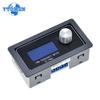
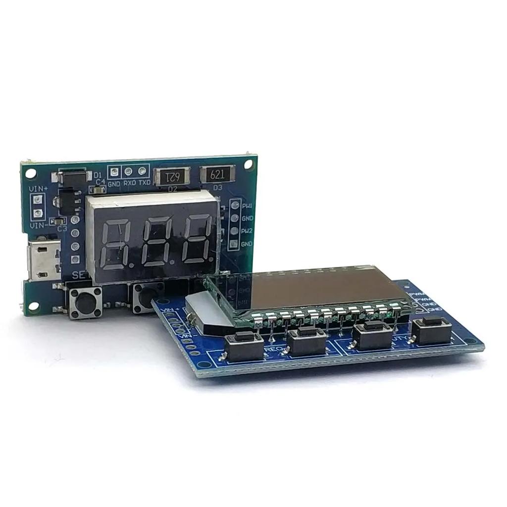
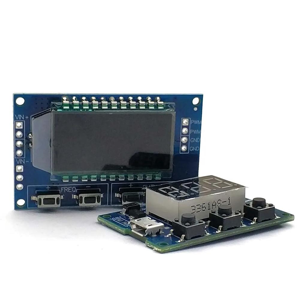
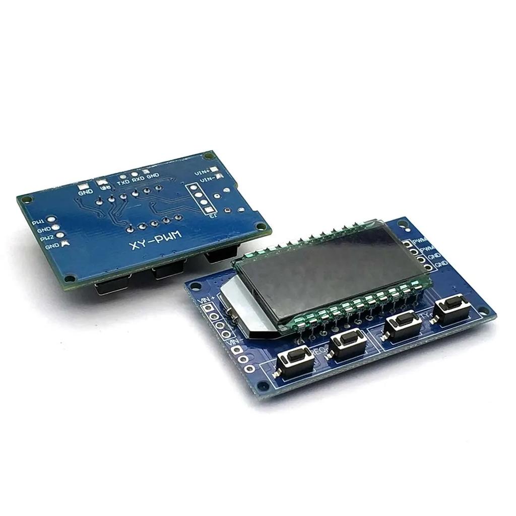
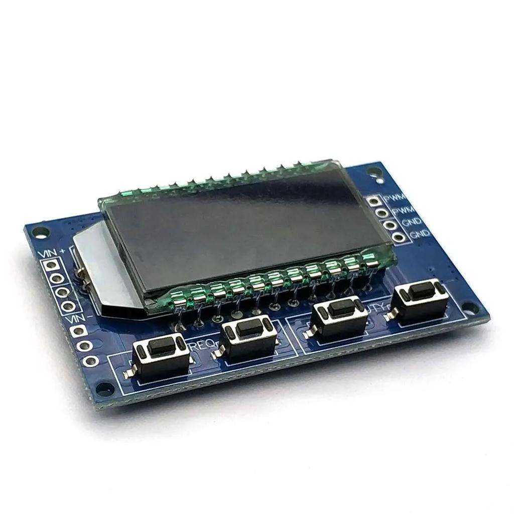
Type 2: 1.LCD display frequency and duty cycle, very clear, PWM output can be set to the frequency and duty cycle; 2. Wide frequency range, high precision; 3. Serial communication, TTL level
Module description PWM output, you can set the frequency, duty cycle; Frequency is divided into four ranges, automatic switching: 1. XXX (no decimal point): the smallest unit is 1Hz, the value range of 1Hz ~ 999Hz; 2. X.XX (decimal point in the hundred) the smallest unit is 0.01Khz, the range of 1.00Khz ~ 9.99Khz; 3. XX.X (decimal point in ten): the smallest unit is 0.1Khz; value range of 10.0KHz ~ 99.9KHz 4. X.X.X (decimal point in ten and hundred): the smallest unit is 1Khz; value range 1KHz ~ 150KHz
Frequency display: 100 indicates PWM output 100Hz pulse; 1.01 indicates PWM output 1.01K pulse; 54.1 indicates that the PWM output has a pulse of 54.1 kHz; 1.2.4 indicates that the PWM output is 124 kHz pulse; Duty cycle range: 0 ~ 100%; All set parameters, power-down automatically saved.
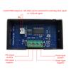
Parameter settings The module has four independent keys, used to set the frequency and duty cycle, support touch (increase or decrease a unit) and long press (fast increase or decrease), set the parameters automatically save, power down Not lost.
Module parameters: 1. Working voltage: 3.3 ~ 30V; 2. Frequency range: 1Hz ~ 150KHz; 3. Frequency accuracy: the accuracy in each range is about 2%; 4. Signal load capacity: the output current can be about 5 ~ 30ma; 5. Output amplitude: PWM amplitude equal to the supply voltage; 6. Ambient temperature: -20 ~ +70 ℃.
Scope of application: 1. Used as a square wave signal generator, generate square wave signal for experimental development and use; 2. Used to generate a square wave signal that controls the motor driver; 3. generate adjustable pulse for MCU use; 4. generate adjustable pulse, control the relevant circuit (PWM dimming speed and other applications). 5, serial control (single-chip TTL level communication)
Communication standard: 9600 bps Data bits: 8 Stop bit: 1 Check digit: none Flow control: none 1, set the frequency of the PWM "F101": Set the frequency to 101 HZ (001 to 999) "F1.05": set the frequency of 1.05 KHZ (1.00 ~ 9.99) "F10.5": Set the frequency to 10.5KHZ (10.0 ~ 99.9) "F1.0.5": set the frequency of 105KHZ (1.0.0 ~ 1.5.0) 2, set the PWM duty cycle "DXXX": set the PWM duty cycle to XXX; (001 ~ 100) Such as D050, set the PWM duty cycle is 50% 3, read the set parameters Send a "read" string to read the set parameters. Set successfully return: DOWN; Setup failed to return: FALL.
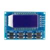
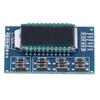
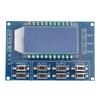
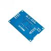
Type 3: Three PWM pulse frequency duty cycle adjustable module square wave rectangular wave signal generator Module highlights:
1. 3 PWM output, frequency adjustable, 3 frequency output consistent, duty cycle can be independently adjusted, suitable for most occasions; 2. LCD display frequency and duty cycle, very clear, very convenient to adjust 3. Wide frequency range and high precision; 4. Serial port communication
I. Module description 3 PWM output, wide frequency range, duty cycle can be independently real-time adjustment; Frequency is divided into four ranges, automatic switching: 1. XXX(without decimal point) : The minimum unit is 1Hz. The value ranges from 1Hz to 999Hz. The minimum unit is 0.01khz, and the value ranges from 1.00khz to 9.99khz; 3. XX.X(decimal place in ten) : the minimum unit is 0.1khz; Value range: 10.0KHz to 99.9KHz 4. X.X.X (decimal place in tens and hundreds) : the minimum unit is 1Khz; Value range: 1KHz to 150KHz
Frequency display: 100 means PWM output pulse of 100Hz; 1.01 indicates that the PWM output is 1.01K pulse; 54.1 represents a pulse of 54.1KHz for PWM output; 1.2.4 Represents the PWM output pulse of 124KHz; Duty cycle Value range: 0 to 100%, where 100% is expressed in A0%. All parameters are saved after power failure. 2. Parameter setting Module has 8 independent keys, used to set the frequency and duty cycle, support short press (increase or decrease a unit) and long press (quickly increase or decrease), very simple, set the parameters automatically save, power loss is not lost. 3 way duty cycle button can be pressed at the same time, real-time adjustment, the liquid crystal display is the last button to press the duty cycle, real time is very strong, can be used for simple several way duty cycle scanning. Iii. Module parameters: Operating voltage: 3.3~30V; 2. Frequency range: 1Hz~150KHz; 3. Frequency accuracy: the accuracy in each range is about 2%; 4. Signal load capacity: the output current can be about 5~ 30mA; 5. Output amplitude: THE PWM amplitude is equal to the supply voltage; 6. Ambient temperature: -20 ℃ to +70℃. Four, the scope of application: 1. Used as a square wave signal generator to generate square wave signals for experimental development; 2. Used to generate the square wave signal to control the motor driver; 3. Generate adjustable pulse for MCU use; 4. Generate adjustable pulse, control related circuit (PWM dimming speed control and other applications). Five, serial port control (MCU TTL level communication) Communication standard :9600 BPS Data bit :8 Stop bits: 1 Check digit: none Flow control: none 1. Set the FREQUENCY of PWM F101: Set the frequency to 101 HZ (001 to 999). "F1.05" : Set the frequency to 1.05khz (1.00~9.99) "F10.5" : Set frequency to 10.5khz (10.0~99.9) "F1.0.5" : set the frequency to 105KHZ (1.0.0~1.5.0) 2. Set the duty cycle of PWM Dx: YYy: sets the duty cycle of PWM x: (1~3) PWM number, YYY: (000-100) duty cycle %; For example, D1:050, set the duty cycle of route 1 PWM to 50% 3. Read the setting parameters Send a "read" string to read the set parameter. Read data in the following format: F156, D1:052, D2:059, D3:058, Returns: DOWN; Failure to set returns: FALL.
Package Included 1 Pcs Signal Generator PWM Pulse Frequency Duty Cycle Adjustable Module